CASS - CAmera aS Scanner
Mar 23, 2020
Hello dear reader,
In the time of COVID-19, there is nothing more to do than Write From Home…
My next few posts are going to be sort of broad spectrum computer vision (CV) stuff that I have found to be very exciting and super functional. Most of these insights have been powered by the indominable, Dr. Amy Tabb (@amy-tabb; https://github.com/amy-tabb/CASS).
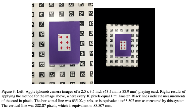
The best place for me to start is with Tabb et al. “Using cameras for precise measurement of two-dimensional plant features: CASS” arXiv:1904.13187v2.
This is a protocol, pre-print that generally describes (e.g., does not go into the deep details) the use of aruco tags and CASS for geometric calibration of digital images. The reason I think this is article is important is simple – iamges are loaded with all kinds of geometric distortion that differs camera-to-camera. PERIOD. If you are like me and you want to measure objects using a images from a camera, because they are fast and relatively cheap, then we should be able to account for all kinds of geometry issues that are inherent to cameras. Flatbed scanners solve the geometry problems, but you are limited to objects that are truly 2-dimensional, and they are very slow.
A single ruler somewhere in the frame doesn’t cut it for calibration (i.e., learning pixels-to-mm-transformation). Ever. I am not convinced by calibration-from-quarter or calibration-from-wire either. Distortion is continuously variable and is different for every pixel and that warping function cannot be learned from a single observation of a ruler, quarter, or wire in a single location in the frame.
One arguement is: If you measured the diameter of a wire along the length of the copper wire in the image or the same quarter in multiple places within an image, you would not have the same error for every measured point. However, if you calibrate entire image, the error should be identical along the length of the wire or for any observation of a quarter. The same thing is maybe more obvious for a ruler. “1cm” measured in the middle will contain a different number of pixels compared to “1cm” at the edges of the ruler, because of the continuous, non-random distortion. The goal, obviously, should be to achieve an equal number of pixels-per-cm no matter what part of the image you are measuring.
I am not sure how we have gotten on that in the plant community, I do it too, but dang it is effectively useless.
Dr. Tabb’s solution allows you to access the benefits of both image acquisition with cameras and geometric accuracy of flatbed scanners. Literally the best of both worlds, IMO. I wish I had known about this process before I started collecting data for my work on strawberry shape. In the future, if I continue to pursue morphometrics of fruit, I will certainly be adopting this method.
From the CASS github repo: “[CASS] takes an image of an object on top of an aruco calibration pattern, calibrates the camera using the detected aruco information as well as EXIF tag information, and undistorts and computes the homography from the current location of the aruco calibration pattern in the image to its location in physical space. Then the image is warped to match the coordinate system of the aruco coordinate system, scaled by a user-selected parameter.” CASS is super easy to install and build from source on MacOS X and Ubuntu 18.04 LTS. I have not tried on windows, but I have a sneaking suspicion that the Docker release will be “more” useful for Windows folks.
This is something you can play around with while you are stuck inside during the Great Toilet Paper Shortage of 2020. Totally a DYI project: camera, printer and paper for aruco marker panel, plant or stand-in plant-like object for imaging, crap computer and internet for software, and your brain. Done. For some existing data check out the Zenodo repository for this project (http://doi.org/10.5281/zenodo.3677473) and just have fun! Simple.
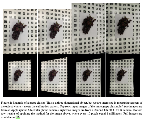
The aruco panel is made up of a white background and black, indexed, data-matrix-like square markers. The purpose of these markers is provide a checker board grid of known size (and shape) and density. Ideally, the camera is positioned directly above (or in front) of the aruco panel. This is likely more important for 3-D objects where occlusion at extreme viewing angles is likely problematic. Calibration doesn’t allow your camera to infer what isn’t seen after all. That is really it. It is that simple. The real beauty of this solution, is that every image, no matter what camera, can be calibrated to the same aruco panel details (just print your panel n-times, or for however many camera set ups you have rolling).
If you know where you nearly black, or nearly white, objects are going to be placed in the frame (difficult to segment given a checkboard background), you could place a blue “landing pad” amidst the aruco markers. As long as there are plenty of aruco markers in the image, the calibration should work well and as long as your objects stand out clearly against your background you will also be able to successfully segment your objects!
Where do we go from here? There are infinite possibilities really, but I think the most promising future direction is full-spectra color calibration. This is perhaps a good topic for my next offering. There are a couple of manuscripts that I have spent sometime reading in this field that I think have both good and bad aspects to them.
Best, Mitchell